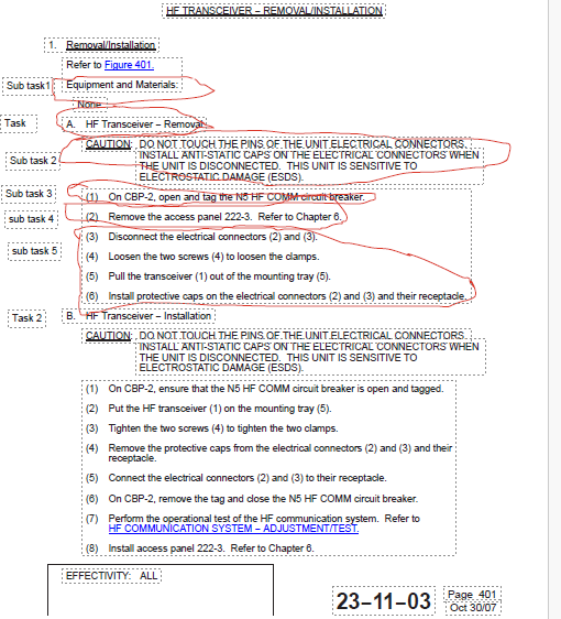
- Removal/Installation
Refer to Figure 401.
Equipment and Materials:
None.
A. HF Transceiver − Removal
CAUTION: DO NOT TOUCH THE PINS OF THE UNIT ELECTRICAL CONNECTORS.
INSTALL ANTI-STATIC CAPS ON THE ELECTRICAL CONNECTORS WHEN
THE UNIT IS DISCONNECTED. THIS UNIT IS SENSITIVE TO
ELECTROSTATIC DAMAGE (ESDS).
(1) On CBP-2, open and tag the N5 HF COMM circuit breaker.
(2) Remove the access panel 222-3. Refer to Chapter 6.
(3) Disconnect the electrical connectors (2) and (3).
(4) Loosen the two screws (4) to loosen the clamps.
(5) Pull the transceiver (1) out of the mounting tray (5).
(6) Install protective caps on the electrical connectors (2) and (3) and their receptacle.
B. HF Transceiver − Installation
CAUTION: DO NOT TOUCH THE PINS OF THE UNIT ELECTRICAL CONNECTORS.
INSTALL ANTI-STATIC CAPS ON THE ELECTRICAL CONNECTORS WHEN
THE UNIT IS DISCONNECTED. THIS UNIT IS SENSITIVE TO
ELECTROSTATIC DAMAGE (ESDS).
(1) On CBP-2, ensure that the N5 HF COMM circuit breaker is open and tagged.
(2) Put the HF transceiver (1) on the mounting tray (5).
(3) Tighten the two screws (4) to tighten the two clamps.
(4) Remove the protective caps from the electrical connectors (2) and (3) and their
receptacle.
(5) Connect the electrical connectors (2) and (3) to their receptacle.
(6) On CBP-2, remove the tag and close the N5 HF COMM circuit breaker.
(7) Perform the operational test of the HF communication system. Refer to
HF COMMUNICATION SYSTEM − ADJUSTMENT/TEST.
(8) Install access panel 222-3. Refer to Chapter 6.